
WARNING:
FUEL SUPPLY LINES WILL REMAIN PRESSURIZED FOR LONG PERIODS OF TIME
AFTER ENGINE SHUTDOWN. THIS PRESSURE MUST BE RELIEVED BEFORE SERVICING
OF THE FUEL SYSTEM IS BEGUN. A VALVE IS PROVIDED ON THE FUEL INJECTION
SUPPLY MANIFOLD FOR THIS PURPOSE.
The fuel charging system consists of the throttle body, and the intake manifold, fuel injectors, fuel pressure regulator and idle air control valve (IAC valve). Prior to service or removal of the fuel charging system perform the following steps:
1. Disconnect battery ground cable.
2. Remove fuel tank filler cap and release fuel tank pressure.
Fuel Pressure Relief
1. Remove engine air cleaner (ACL).
2. Connect Multiport Fuel Injection (MFI) Fuel Pressure Gauge (EFI/CFI)
T80L-9974-B to the fuel pressure relief valve on the fuel injection supply
manifold.
3. Open the manual valve on the gauge to relieve fuel system pressure.
Removal
1. Disconnect battery ground cable.
2. Disconnect crankcase ventilation tube and aspirator hose from air cleaner outlet tube. Loosen engine air cleaner tube clamps and remove air cleaner outlet tube.
3. Remove retaining bolts and accelerator cable shield from throttle
body.
4. Disconnect accelerator cable and speed control actuator cable from
throttle body lever.
5. Remove two accelerator cable bracket retaining bolts from throttle
body. Position accelerator cable bracket, accelerator cable and speed control
actuator cable out of the way.
6. Disconnect wiring connections for the engine control sensor wiring
from the idle air control valve (IAC valve) and throttle position sensor
(TP sensor).
7. WARNING: ENGINE COOLING SYSTEM MAY BE UNDER PRESSURE. RELEASE PRESSURE
AT RADIATOR CAP BEFORE REMOVING HOSES.
Remove water bypass hoses from the throttle body.
8. If required, remove the idle air control valve and gasket from the
surge tank connector. Discard gasket.
9. Remove the throttle body retaining nuts and bolts (note location
for installation).
10. Remove throttle body from surge tank connector. Discard gasket.
11. Discard throttle body gasket (TB gasket).
Installation
1. CAUTION: Use care when cleaning gasket material because aluminum gouges easily which forms leak paths.
Note: If scraping is necessary, do not damage gasket surfaces or allow gasket material into intake manifold.
Clean and inspect sealing surfaces of surge tank connector and throttle body.
2. Install new throttle body gasket.
3. Position throttle body and install retaining bolts and nuts. Tighten to 16-23 N-m (12-16 lb-ft).
4. If removed, install idle air control valve with a new gasket to the surge tank connector. Tighten retaining bolts to 9.5 N-m (84 lb-in).
5. Connect water bypass hoses and position clamps securely. Refill engine cooling system.
6. Connect wiring connectors for engine control sensor wiring to the throttle position sensor and idle air control valve.
7. Install accelerator cable bracket to the throttle body. Tighten retaining bolts to 17 N-m (12 lb-ft).
8. Connect accelerator cable and speed control actuator cable to the throttle body lever.
9. Install accelerator cable shield. Tighten retaining bolts to 1.4 N-m (12 lb-in).
10. Connect air cleaner outlet tube to the throttle body and engine air cleaner (ACL). Tighten engine air cleaner tube clamps to 1.4-2.5 N-m (13-22 lb-in).
11. Connect crankcase ventilation tube and aspirator hose to the air cleaner outlet tube.
12. Connect battery ground cable.
13. Start engine and check for vacuum and engine coolant leaks.
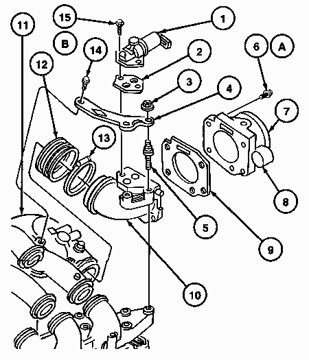
| Item | Part Number | Description |
| 1 | 9F715 | Idle Air Control Valve |
| 2 | 9F670 | Gasket |
| 3 | -- | Nut (2 Req'd) |
| 4 | 9J444 | Intake Manifold Support |
| 5 | -- | Stud Bolt (2 Req'd) |
| 6 | -- | Bolt (4 Req'd) |
| 7 | 9E926 | Throttle Body |
| 8 | 9B989 | Throttle Position Sensor |
| 9 | 9E936 | Throttle Body Gasket |
| 10 | -- | Surge Tank Connector |
| 11 | 9424 | Intake Manifold |
| 12 | 9F722 | Air Tube to Throttle Body Hose |
| 13 | -- | Surge Tank Connector Hose Clamp (2 Req'd) |
| 14 | -- | Flange Bolt |
| 15 | -- | Bolt (2 Req'd) |
| A | -- | Tighten to 16-23 N-m (12-16 Lb-Ft) |
| B | -- | Tighten to 9.5 N-m (84 Lb-In) |
FUEL INJECTION SUPPLY MANIFOLD
Removal
1. Remove intake manifold
.
2. WARNING: FUEL SUPPLY LINES WILL REMAIN PRESSURIZED FOR LONG PERIODS
OF TIME AFTER ENGINE SHUTDOWN. FUEL SYSTEM PRESSURE MUST BE RELIEVED PRIOR
TO FUEL SYSTEM SERVICE TO PREVENT POSSIBLE INJURY. REFER TO FUEL PRESSURE
RELIEF.
Disconnect fuel line spring lock couplings.
3. Disconnect connectors from engine control sensor wiring at fuel injectors. Disconnect vacuum hose at fuel pressure regulator.
4. If required, remove fuel pressure regulator and fuel pressure relief valve from the fuel injection supply manifold as described.
5. Remove four retaining bolts and remove fuel injection supply manifold.
Installation
1. WARNING: ALWAYS USE NEW O-RINGS WHEN ASSEMBLING FUEL INJECTION SUPPLY MANIFOLD COMPONENTS TO AVOID COMBUSTION FROM FUEL LEAKAGE.
Install fuel injection supply manifold, and make sure all fuel injectors are properly seated.
2. Install four fuel injection supply manifold retaining bolts. Tighten to 15-23 N-m (11-16 lb-ft).
3. If removed, install the fuel pressure relief valve and fuel pressure regulator to the fuel injection supply manifold as described.
4. Connect engine control sensor wiring at fuel injectors.
5. Connect fuel line spring lock couplings as described.
6. Install intake manifold.
7. Connect vacuum line to the fuel pressure regulator.
8. Run engine and check for fuel leaks.
Fuel Injection Supply Manifold
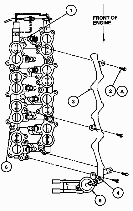
| Item | Part Number | Description |
| 1 | 9F593 | Fuel Injector (8 Req'd) |
| 2 | 9S824-06012 | Bolt (4 Req'd) |
| 3 | 9D280 | Fuel Injection Supply Manifold |
| 4 | 9H321 | Fuel Pressure Relief Valve |
| 5 | 9C968 | Fuel Pressure Regulator |
| 6 | 9424 | Lower Intake Manifold (IMRC) |
| A | -- | Tighten to 15-23 N-m (11-16 Lb-Ft) |
Removal
1. Remove intake manifold.
2. Perform Fuel Charging System Pre-Service procedure and Fuel Pressure Relief procedure described above
3. Disconnect connectors from engine control sensor wiring at fuel injectors.
4. Remove fuel injection supply manifold retaining bolts.
5. Raise and slightly rotate fuel injection supply manifold and remove fuel injectors.
Installation
1. Inspect fuel injector O-ring seals for damage or deterioration. Replace if necessary.
2. Lubricate fuel injector O-rings with clean engine oil meeting Ford specification WSS-M2C153-F.
3. Install fuel injectors in fuel injection supply manifold. Lightly twist and push fuel injectors into position.
4. Install fuel injection supply manifolds and make sure fuel injectors seat properly in cylinder heads.
5. Install fuel injection supply manifold retaining bolts. Tighten to
15-23 N-m (11-16 lb-ft).
6. Connect engine control sensor wiring at fuel injectors.
7. Install intake manifold.
8. Perform Post-Service Procedures described below.
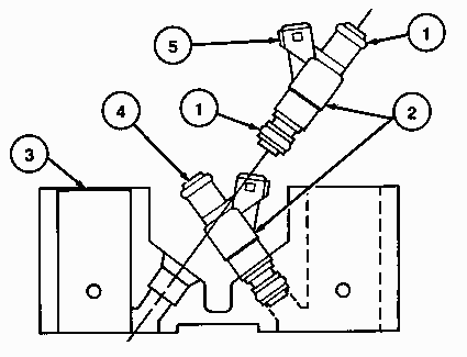
| Item | Part Number | Description |
| 1 | 9229 | Fuel Injector O-Ring (16 Req'd) |
| 2 | 9F593 | Fuel Injector (8 Req'd) |
| 3 | 9424 | Lower Intake Manifold (IMRC) |
| 4 | -- | To Fuel Injection Supply Manifold |
| 5 | -- | Electrical Connector (Part of 9F593) |
Removal
1. If removing fuel pressure regulator with fuel injection supply manifold installed in vehicle, Fuel Pressure Relief procedure as described above.
2. Disconnect vacuum hose at fuel pressure regulator.
3. Remove fuel pressure regulator from fuel injection supply manifold and discard used sealing O-rings and face seal.
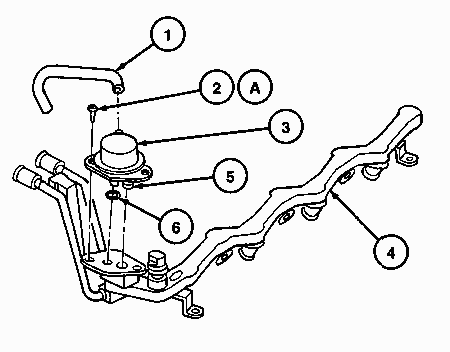
| Item | Part Number | Description |
| 1 | -- | Fuel Pressure Regulator Vacuum Hose |
| 2 | -- | Screw (2 Req'd) |
| 3 | 9C968 | Fuel Pressure Regulator |
| 4 | 9D280 | Fuel Injection Supply Manifold |
| 5 | -- | O-Ring (2 Req'd) |
| 6 | -- | Gasket |
| A | -- | Tighten to 25-34 N-m (19-25 Lb-Ft) |
Installation
1. Install fuel pressure regulator into fuel injection supply manifold using new sealing gaskets, O-rings and face seals. Tighten fuel pressure regulator to 25-34 N-m (19-25 lb-ft).
2. Connect vacuum hose to fuel pressure regulator.
3. Follow Post-Service Procedures, below.
After the service is complete and the fuel charging system is installed onto engine, perform the following steps:
1. Install fuel tank filler cap at fuel tank.
2. Connect battery ground cable.
3. Add engine coolant (if required).
4. WARNING: THE FUEL SYSTEM IS NORMALLY PRESSURIZED TO 276 KPA (40
PSI). USE CARE WHEN SERVICING THE FUEL SYSTEM OR PERSONAL INJURY MAY OCCUR.
Note: Check all connections at fuel injection supply manifold, fuel
injectors, push connect fittings, etc. Turn ignition switch ON/OFF several
times without starting engine and check for fuel leaks.
5. Start engine and warm to operating temperature. Check for engine
coolant leak if coolant was removed.