
new 3/12/03
see also part 1 -teardown
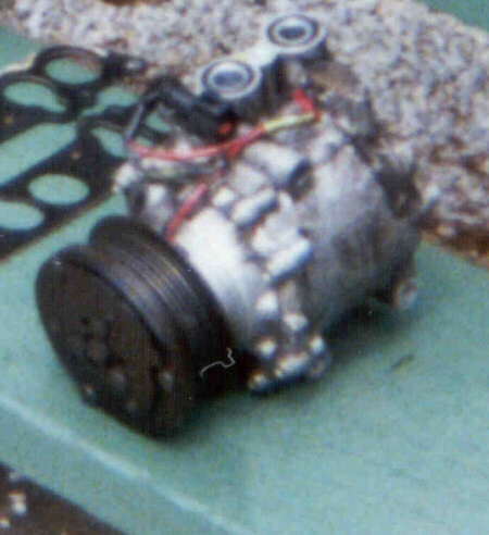 |
A/C Compressor |
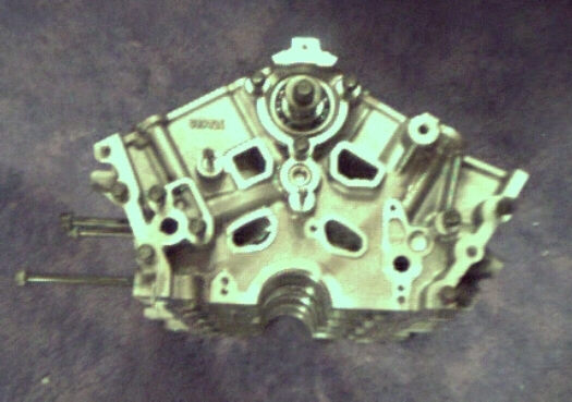 |
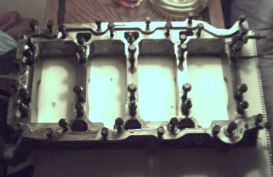
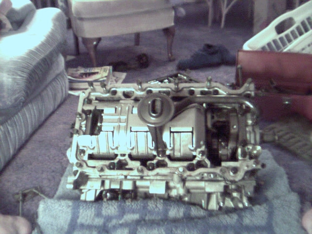
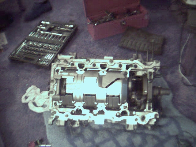
This is the front of the block after being completely disassembled. The only thing left in it is the balance shaft. You can tell this block is meant for racing. It's cast for purpose. It's extremely light weight and very small. The bolts on the side are for the alternator bracket. It's bolted to the side of the block. The aluminum is also very soft. It's not very hard to put a nick or mark into it. |
| A picture of the crank. Each connecting rod has it's own rod journal. They are on the same throws but they are offset slightly. It's a fairly beefy unit. The counterweights are huge! The end of the crank has 8 bolts. There isn't any balance to it like a 5.0 V8. It's all internally balanced with help from the balance shaft | |
| Another clearer picture of the crank. You can see in cross drilling of the crank a little better in this picture. The mains and the rod journals have been cross drilled at the factory for better oiling of the mains and the rod journals. One less machining process I won't have to pay for! | |
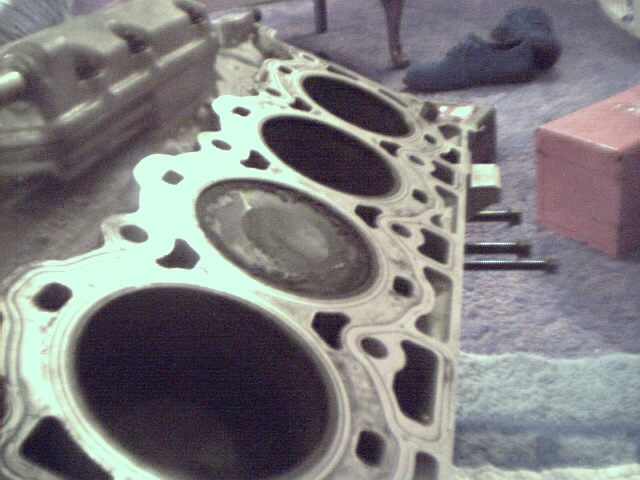 |
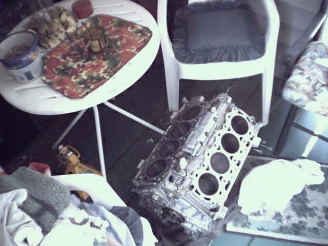
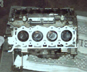
Here is a great picture of the block deck and the disked piston. There are no valve reliefs, only a small dish to reduce compression slightly. They head's have a 39cc combustion chamber and with a flat top piston the compression would probably be 10.5 or 11.0:1. You can see all the coolant holes where the coolant enters from the heads. The 3 large holes you see along the bottom of the block(right side) are the oil drain holes. The oil that goes up into the heads are then drained down into the oil pan through those holes. |
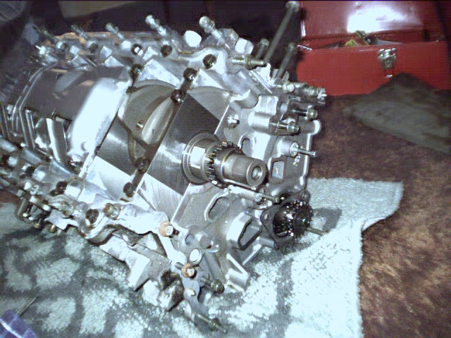 |
This is the number one main of the block. It's VERY thick. It's looks like the mains you see on the Ford Racing Performance Parts R302 race bred block. This would be even stronger as all the mains are connected together as a main girdle tying them all the mains together. You can see it contains 4 bolts on the front main bearing journal. All the journals are like that, as well as having extra bolts along the edge of the girdle. This effectively makes it a 6 bolt main block. You can also see the windage tray installed on the rear part of the motor. I believe this is probably a Duratech V6 part as it only covers 6 rods and doesn't cover the front part of the block to cover all 8 rods. Yes, this is in my living room! I did this while the wife was away for the week. She would kill me if I had done it while she was here! |
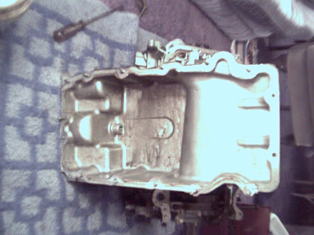 |
This is the inside of the oil pan. Nothing special here. Standard Ford pan, no baffles or anything. When the motor gets put back together a couple baffles will be welded into the sump around the oil pump pickup. That way when extreme corning occurs all the oil will not slosh away from the pick up and allow the pump to start sucking air. It's a pretty elaborate piece just for an oil pan. It's not stamped steel or aluminum. It's cast aluminum. It's a lot heavier than the old 351W oil pan I used to have in the 81 RSX. |
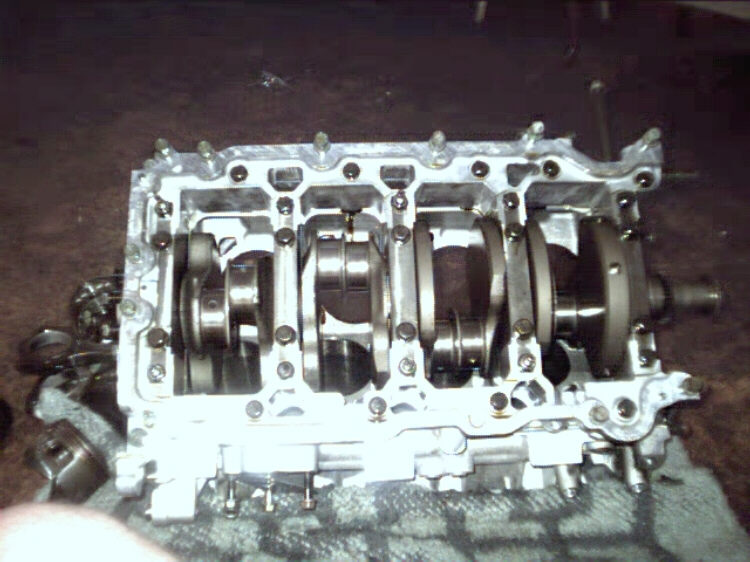 |
Here is the crank installed in block. The rods and pistons have been removed. This shows the rod journals being split as well. You can also see all the bolts holding down the mains as well as the extra bolts along the edge of the girdle bolting it all together. I don't know if you can or not but looking into the bottom of the block you cannot see the balance shaft. It's totally enclosed within the block. The only place you can really see it is through the top of the block where the oil separator is installed. If you look at the bottom of journals 2, 3 and 4 you can see some holes there. Those are the oil return holes to the oil pan. The oil comes outside of the heads dropping through them through the block then the main journal/girdle and finally into the pan. They holes from the block to the girdle are SEVERELY mismatched. The holes in the girdle are much larger than what's in the block. I won't be matching these together. This would take meat away from the journals on the block and probably weaken it. |
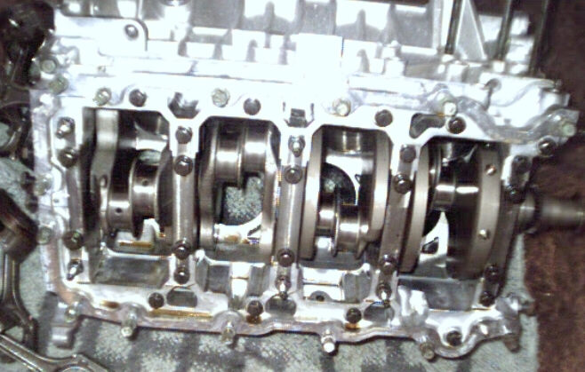 |
Another angle on the inside of the short block. You can see some of the cross drilling on the rod journals as well as some oil drain back holes in the block up inside the block where some of the counterweights are. Along the side of the outside of the block you can see some of the webbing. |
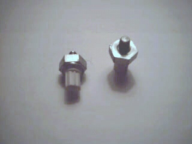 |
Knock Sensors. They won't be used in our application unless the ignition system I get can take advantage of them but I doubt it. There are two, one in the front and one in the back of the block. Some people on the V8 SHO mailing list that their motors ping on 87 octane fuel. These might be the problem. If they are not sensitive enough or not working the computer will not pull timing out and the motor with detonate. It's my contention with such small combustion chambers, high 10:1 compression and a high revving nature, 93 octane or higher should be used. With the propane we are using octane won't be a problem. It's rated at 110. |
 |
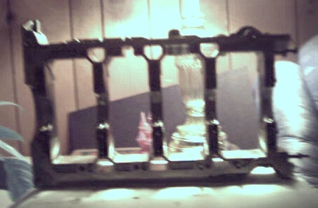
It's always hard to describe this thing. This is the bottom of the motor. On most motors all the main bearing journals that hold the crank in are separate. On motors like the 5.0 V8 from the Mustang, all the mains are separated. In the SHO V8 they are all tied together. This strengthens the bottom end of the motor by tying all the mains together to one main web. This resists the mains from walking and allowing a spun bearing and all other kinds of problems. With the kind of power we'll be making, this will help it all stay together. |
| Another picture of the mains/girdle from the bottom of the motor. This is showing it from the side. It's pretty thick with a lot of webbing. You could say the block is two pieces. The main upper and the lower pictured here. | |
 |
|
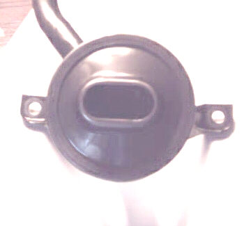 |
The oil pickup that sits on the oil pan. |
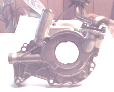 |
The oil pump. This is a gerotor design. It is bolted to the front of the crank snout and is turned by the crank. It's supposed to be VERY efficient. You can see how it's indexed to the crank and the pick up is bolted to the pump. |
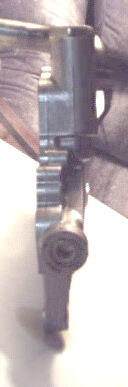 |
The oil pump from the side. It's very thin to fit between the front main and front cover. |
| This is the complete oil pump assembly. It will be completely replaced when the motor goes back together. The motor had an oiling problem to begin with and replacing the pump and pick up would be cheap insurance. I don't know how I will be able to prime the motor before I start it up. | |
 |
Oil Separator. This is actually a part of the PCV System. It helps take out the gases and pressure from in the block and let's it circulate back through the motor to be burnt and sent out the exhaust. |
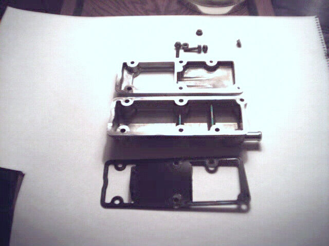 |
Oil Separator opened up. |
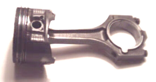 |
Here is the piston and rod assembly. The piston is a short skirt design. The compression height is approximately 1.18". That is pretty small. This means that the pin that holds piston to the rod is 1.18" from the center of that pin to the top of the piston. Besides the other Duratech engines(2.5 & 3.0 V6), this is the only engine I know with a short skirt. Again, comparing it to the 5.0 V8, the compression height is around 1.7". Alot of stroked motors use these types of pistons. This causes the piston to rod a little more than the normal longer skirt pistons. Looking at the picture you can see the smudge on the piston skirt showing that the skirt has been contacting the cylinder wall. This is a piston with only 13,000 miles on it. The rod/ratio of this motor is 1.7" as well. This is a very favorable rod ratio. The piston is held on to the connecting rod with spirolox. The piston is held on with a full floating pin, not a pressed pin. This is how most race car pistons are assembled to allow quick changing of the pistons on the rods. I was able to easily remove the pin and separate the piston from the rod. This rod is a powered forged connecting rod. They take the powered and press it together at high pressure to make the rod. They then break the big end of the rod and bolt it back together. This supposedly makes the rod stronger. It also makes the rod unusable when it's been removed from the engine. The bolts are stretch-to-yield bolts which also makes them "use once" designs. I've seen people reuse this types of bolts over again though. As long as you don't stretch them past their stretch point they should be ok. We'll be replacing them anyways with lightweight aluminum rods. As you've seen in a lot of the other photos this motor was put together and designed like a race engine. Light weight, lots of webbing, short skirt pistons, full floating pistons. |
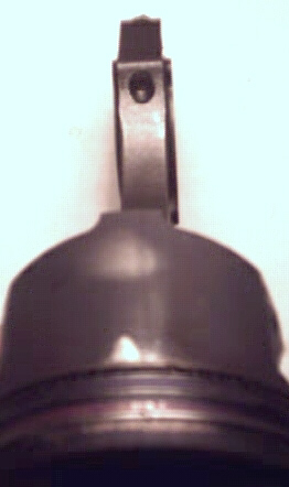 |
The bolts are stretch-to-yield bolts which also makes them "use once" designs. I've seen people reuse this types of bolts over again though. As long as you don't stretch them past their stretch point they should be ok. They will be replaced however with something stronger. These bolts aren't like most rod bolts either. Most rod bolts are pushed in through the top of the rod and them the cap is put on and a nut is then used to secure the cap. On these the cap is put onto the rod and the bolt is screwed in from the cap side and the rod on top is threaded for the bolt. Again, another race feature of the SHO V8. |
 |
This is a picture of the short block, in my living room, with the oil pan off. You can see how it's all crammed in there under the oil pan. The oil pick up, the windage tray and the pickup for the oil pump which leads to the front of the block. |
 |
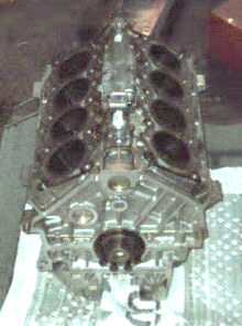
The complete short block outside on the front porch. I put it there after I disassembled it down to it's 175 pound weight. You can see how small this engine really is. The deck is close to the main block. I think this is a good design for strength. This motor almost seems bomb proof. |
 |
This is the short block from the back (driver's side) of the motor. You can see all the webbing on the back and the thick flange of the rear of the crank. The plug in the center top of the rear of the block is where the rear bearing of the balance shaft is. The little tunnel on the bottom of the oil pan is where the drain plug is. |
 |
Again, the short block. This is from the side. The long bolts on the bottom of the left hand side of the picture are for the A/C compressor. You can see the dishes in each of the pistons from the view and lighting. You can see the oil separator assembled. Removing it shows a small view of the balance shaft. You can also see the knock sensors installed on either side of the oil separator. |
 |
Windage tray installed on the short block. This shows it attached without the oil pump or pick up in the way. Oil falls over the crank and lands in the tray. It then falls into the pan from the whole on the left. The purpose of the windage tray is to keep oil from wrapping around the crank and aerating the oil. This allows the crank to spin without the added drag of the oil wrapping itself around the crank. This adds a few HP. Also this is something I won't need to get fabricated as I can use the stock one! |
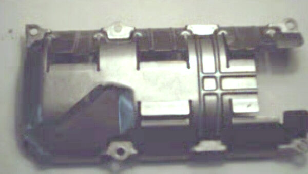 |
Windage tray removed. |
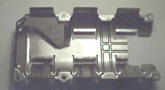 |
Windage tray removed showing the inside. |