Home
| Mailing
List | Specifications | Care
and Feeding | Modifications | Vendors
| Literature

Cam Weld Procedure
new 11/12/02
V8sho cam welding procedure
performed 11-7-02 on 97SHO at approx. 63k miles
(Note: I find "front & rear" and "right and left" to
be ambiguous with a transverse engine layout. For purposes of this writeup I
will try to be more specific. If I say front or rear or right or left, this will
be as if I am standing in front of the car looking directly at the engine. If I
say left bank, then that is the bank of cylinders closest to the front bumper,
and right bank will mean the bank of cylinders closest to the firewall.)
There are procedures on the v8sho.com website for removing the intake and
valve covers. I believe the procedure listed below is fairly direct and removes
the least amount of parts.
Almost all of this work can be done with an 8mm standard socket, a 10mm deep
socket, and a 12mm wrench, also a standard flat blade screwdriver. There was one
nut that required an 11mm wrench. There are a few misc. cable connections that
you must remove that I haven’t specifically mentioned, but they are obvious.
Also you will note that some bolts have studs on top and others don’t. I would
recommend having a pencil and paper handy to make some notes as to where the
bolts with studs go. From start to finish this took 9 hours, which includes a
couple of breaks to clean up and take photographs, breaking for lunch, waiting
for the car transporter, and waiting for the welders to be available and get
their equipment setup.
- Disconnect battery
- Remove appearance cover. I also removed the cover over the big wiring
harness that goes across the front top of the engine but actually it may not
be necessary to remove this.
- Remove upper part of rear set of intake runners. There are about 5 bolts
into the plenum plus the 4 hose clamps.
- Remove entire set of intake runners serving the front bank of cylinders.
This will involve 2 long bolts that go through the throttle body and also
attach a brace that extends to the plenum. You also must remove a similar
brace on the left side of these intake runners.
- Remove lower part of intake runners serving rear bank of cylinders.
- Remove the intake plenum (otherwise called the expansion chamber). This
will have 3 large and 2 small vacuum hoses connected to it, as well as the
EGR. Note that there is a small gasket between the EGR and the plenum. When
you loosen both bolts and remove one of them, the gasket will probably swing
around the remaining bolt and hand below the EGR. You better grab onto it
and hold on because if it drops it will be caught somewhere between the
intake and the transmission and will take you a long time to find. I know
because it took me a long time to find it. You will also need to remove 2
bolts from the long braces that attach to the side of the plenum against the
firewall, 1 bolt per brace. I did this with a 12mm box end wrench. Somebody
mentioned using a ratching box end wrench which might make the job go a
little faster. Last there is a small bracket attached to the drivers side
end of the plenum and another bracket attached to the firewall side of the
plenum. You should be able to loosen the hose clamp to the throttle body and
remove the plenum. Somebody said you could remove the airhorns for
safekeeping prior to removing the plenum. I didn’t see why this would be
necessary. They seem to be pretty well contained in the plenum and trying to
remove them probably involves more risk of problems than leaving them in
place.
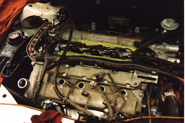
- Now you can actually see both valve covers. Remove the IMRC (3 bolts) and
the wires and 8 ignition coils. The IMRC linkage doesn’t have to be
disconnected- you can set it over by the battery temporarily and it won’t
be in the way of removing the valve covers.
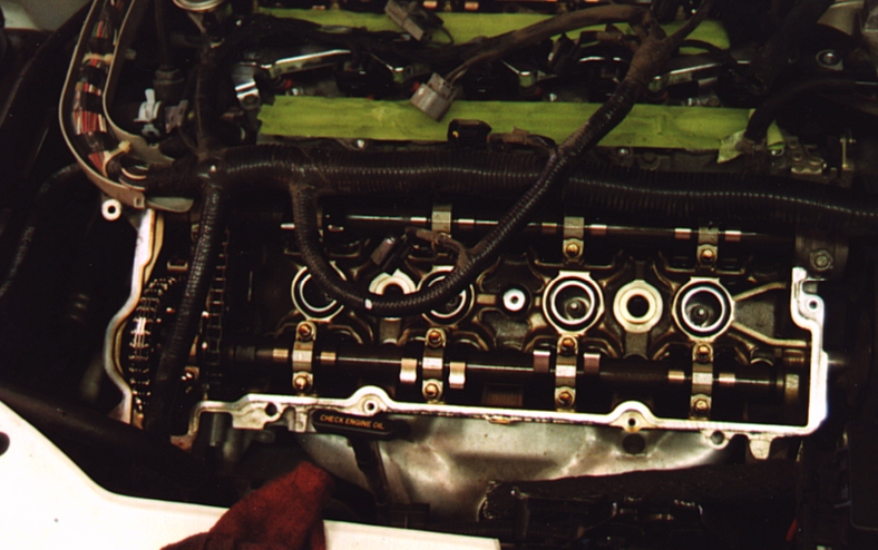
- Remove the valve cover bolts and you can remove the valve covers. There is
a massive wiring harness that goes over the front part of the engine and
somewhat traps the valve covers in place. I traced the harness where it goes
between the engine and radiator and discovered a connector that is clipped
to the A/C compressor holding the wires in place and making it difficult to
get any slack in the harness. I pulled this connector away from the A/C
compressor and got enough slack to remove the front valve cover without
having to disconnect the wires. The back valve cover came off a little
easier. The gaskets were not damaged and seemed to be easily reusable. There
are 2 spots on the back valve cover and 4 on the front valve cover where RTV
was used during original engine assembly. You will need to clean off these
dabs of RTV and note their locations so you can reapply dabs of RTV when you
reassemble the engine. Also note that the valve cover gaskets don’t stick
to the valve covers real tightly so when maneuvering the valve covers back
into position it would be easy to knock the gasket out of alignment. I
recommend double-checking the gasket at the last minute. After maneuvering
the valve cover back into position, after all of the big obstacles are
cleared you will be able to hold the valve cover up 1-2" above the head
and run one of your fingers all the way around the edge of the valve cover
to feel that the gasket is where it should be.
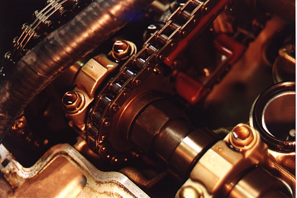
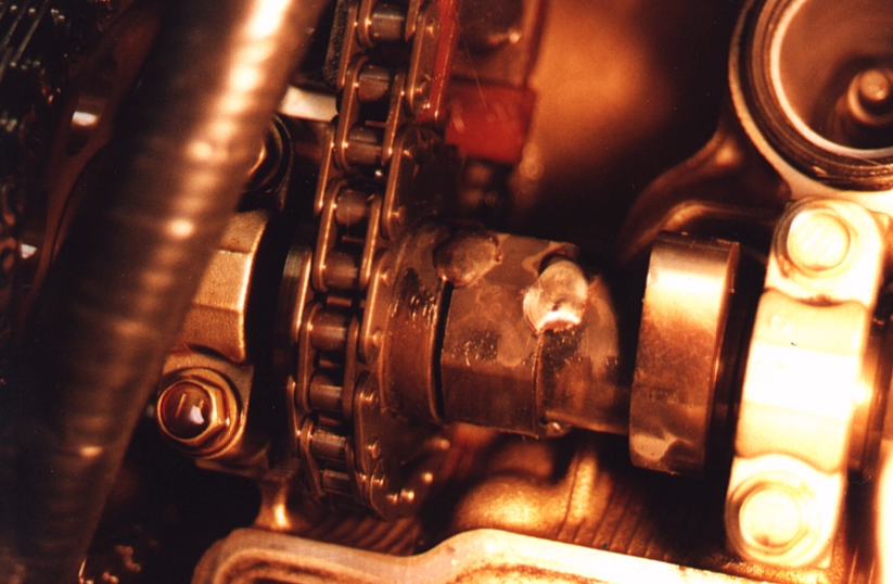
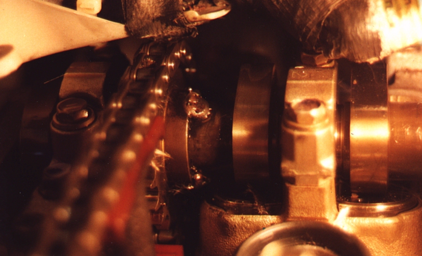
- With the valve covers removed you are ready to start welding. We loaded my
car on the car transporter and carried it to the welding shop. The welder
put stainless wire in his MIG welder and switched it to a cylinder of mostly
Helium gas. He got a couple of pieces of 1/8" carbon steel and did some
test welds to get his welder settings right. I showed him where to weld and
told him that most people had recommended ¼" or ½" beads of
weld, at 3 locations around the perimeter of the camshaft. We were concerned
about heat input so we actually did something a little less than ½"
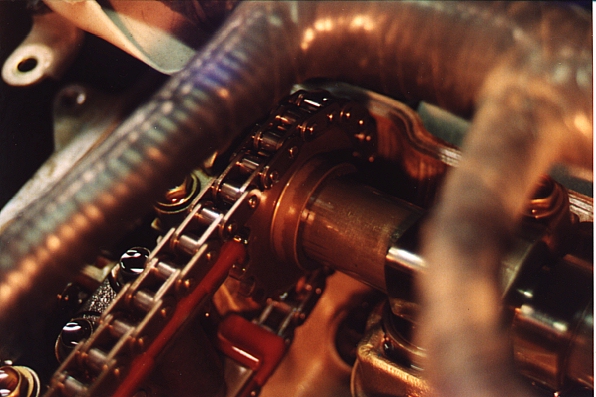
beads. We cut up an old welding blanket and packed pieces and strips around
the cams and under them as best we could to block welding debris. However
the welding blanket was stiff and less than ideal. I think it would be
better to use damp rags which would conform better to the shapes of the
engine. I think it would be important to block as much debris as possible
from getting into the engine although I don’t think there is any way to
prevent it all from getting in there. We welded 5 spots, bumped the engine
to rotate the cams, welded 5 more spots, then bumped and welded the last 5
spots. We wiped off the surfaces with a rag but still seemed to have a
little trouble with oil under the gears so it might be advisable to use
something to blow the oil out of the spaces first.
- We hauled the car back to the garage and put it all back together. I laid
all of the bolts out on a table and grouped them according to size and
length which helped to figure out which size and length of bolts went back
where. I ended up without any leftover pieces which is always good. I wiped
off all of the gaskets before reassembly. The gaskets and airhorns going to
the plenum are a bit tricky to line up and keep lined up. It might be
advisable to put a few dabs of gasket cement on to hold things in position
while you install the intake runners.
Thanks to Billy James
Contact Information