
| The 1996 to 1999 SHO's are equipped with a feature known as Semi-Active Ride Control. The vehicle's computer receives information from sensors on the struts and makes adjustments in ride quality to compensate for road conditions. This is a procedure for installing a switch that cuts out the semi-active ride control on the 1996 Ford Taurus SHO. By doing so, the suspension is set to "full hard" and the amount of power steering assistance is reduced. The author makes no claims or guarantees that this modification will work properly for any vehicle. If you choose to modify your vehicle based on these instructions, you do so at your own risk. Installation of this modification could damage your vehicle or void your warranty. Since I don't have a warranty, I don't particularly care. | What you will need:
Cost: $0.00. I had everything I needed in my tool box! |
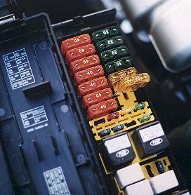
| Step 1: Fuse Location
Open the hood of the car and locate the black plastic Power Distribution Box, between the battery and the hood latch at the front of the car. Pull the tabs on both sides of the box's cover to reveal the fuses and relays underneath. Remove the 20 amp yellow fuse that controls the SARC as indicated in the image to the left. For reference, it is the bank of fuses closest to the motor. There are four green 30 amp fuses, followed by two yellow 20 amp fuses. The first 20 amp fuse that sits next to the 30 amp fuses controls the fuel pump. The SARC fuse is the next 20 amp fuse after that. (Side note: I had it all wired up and when I started the car and hit the switch, the car stalled. Not bad for an anti-theft device, but hardly the result I wanted. Make sure you pull the correct fuse!) |
 |
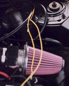
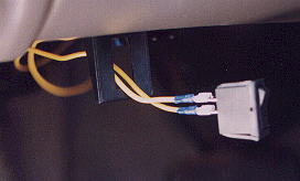
| Step 2: Running the Wire
Go inside the cabin and look up under the dash board on the driver's side of the car. With the hood open, you should be able to see light coming from the outside. It's pretty far up on the fire wall and you may have to bend and twist yourself to see it, but it's there. From under the hood, the location is way back against the firewall, just to the left and behind the strut tower. This is the grommet I used to run the wires through the fire wall. Cut the 12 foot length of wire into two equal sections. Straighten the metal coat hanger and tape two ends of the two wires to one end of the coat hanger. Fish the coat hanger through the grommet in the fire wall. Just aim it for the light and it will find it's way there. Once through the fire wall, go under the hood and see where it came out. It should come out right by the driver's side strut tower. As shown in the image to the right, pull a good length of the wire through the fire wall making sure that you leave enough wire to work with in the cabin. |
 |
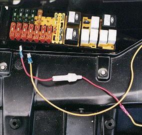
| Step 3: Installing Connections
Install the 20 amp fuse in the in-line fuse holder if it hasn't been done already. Strip back the coating on both ends of the in-line fuse wire, and both ends of the wire you pulled through the fire wall; about 1/4 inch of exposed wire is sufficient to make a decent connection. Crimp one of the male blade connectors onto one of the wires you pulled through the fire wall and move it aside for now. Now the other wire. Crimp one end of the butt connector onto the remaining wire that came through the fire wall. Now, crimp the other end of the butt connector onto one end of the in-line fuse wire. Then crimp the other male blade connector onto the other end of the in-line fuse. (Awwwwww, just look at the picture and figure it out!) Using the electrical tape, cover the butt connector by wrapping the tape around the splice and some of the wire. |
 |
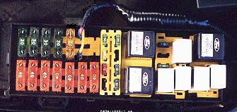
| Step 4: Inserting Connections
Take the two wires with the male blade connectors attached and insert one male connector into each of the two slots where you removed the large yellow 20 amp fuse. Reference the image to the left. It does not matter, at least to me, which blade connector goes into which slot. Now gently bend both wires towards the motor and fasten them together with a piece of electrical tape. Take the Power Distribution Box cover and align it with the box as if you were going to put the cover back on. Note that the wires you installed will prevent you from attaching the cover. Locate the area on the box cover where the wires run out of the box. Using the utility knife, make a notch in the cover that will allow the wires to feed through the cover when it is installed. Now, dress the wire in. I wrapped both lines with electrical tape and then covered that with black plastic wire loom. This just looks better than a bunch of wire running loose under the hood. Starting at the box, tuck the wire around the battery, under the air filter, and in front of the strut tower. Use the zip-ties to secure the wires to the car. |
 |
| Step 5: Switch Connection
Back inside the cabin, locate the remaining wire that you pulled through the fire wall. What you do for a switch and mounting it is optional here. I had an old, unlighted (2 prong) fog light switch laying in my tool box, so I used that. What you don't want is a lighted switch which has three prongs. If you ground the third prong the light will come on and stay on when the car is in it's normal operating mode for everyday driving. The light will only go out when you flip the switch to put the suspension in "full competition mode." Any ways; I located the lower left bolt that holds on the lower steering column cover. I loosened this bolt, slid the switch bracket on, and tightened the bolt. Run the loose ends of the wires through the opening in the switch bracket. Strip 1/4 inch of the coating off both wires and crimp on the female blade connectors. Press the blade connectors onto the terminals on the back of the switch. Now, press the connected switch into the bracket. Lastly, bundle up any loose wire hanging down and zip-tie it up underneath the dash somewhere so it's out of the way. |
 |
| Step 6: Test Drive!
|
What you will notice: 1st; how much you love this
car!!! 2nd; this really stiffens the suspension. I started
the car and turned the wheel left and right a few times; the switch was
off. I stepped out and put some pressure on the front and rear corners
of the car, getting it to bounce a little. Flip the switch and the
power steering assist was noticeably decreased. Tried the bounce
test again . . . nadda. Solid as a rock! 3rd; the test drive
revealed that with the SARC switch in "full competition mode" the ride
is too harsh for my "everyday use." You do get bumped around quite
a bit and it stiffened suspension does make stuff rattle that didn't before.
I can't wait for the next autocross!! 4th; steering response is a
little more immediate. A definite plus all the way around.
. Now if I could find a ride control switch out of a Super Coupe in a junk yard, it would almost look stock ;) |