
new 4/10/03
|
Article No.
01-9-7 |
|
| Publication Date: MAY 3, 2001 | |
|
FORD:
|
1994-97 THUNDERBIRD 1994-2001 MUSTANG 1995-2001 CROWN VICTORIA 1996-97 PROBE 1996-2000 CONTOUR 1996-2001 ESCORT, TAURUS 2000-2001 FOCUS |
| 1994-97 F SUPER DUTY, F-250 HD, F-350 1995-2001 ECONOLINE, RANGER, WINDSTAR 1996 BRONCO 1996-97 AEROSTAR 1996-2001 EXPLORER 1997-2001 EXPEDITION, F-150, F-250 LD 1999-2001 SUPER DUTY F SERIES 2000-2001 EXCURSION 2001 ESCAPE |
|
|
LINCOLN:
|
1995-2001 CONTINENTAL, TOWN CAR 1996-98 MARK VIII 2000-2001 LS |
| 1998-2001 NAVIGATOR | |
|
MERCURY:
|
1994-97 COUGAR 1995-2001 GRAND MARQUIS 1996-99 TRACER 1996-2000 MYSTIQUE 1996-2001 SABLE 1999-2001 COUGAR |
| 1997-2001 MOUNTAINEER |
This article is intended to be an aide in diagnosing conditions related to Heated Oxygen Sensor (HO2S), Catalyst, and Fuel System Monitor related Diagnostic Trouble Codes (DTCs). Additional information is included to assist in diagnosing certain vehicle symptoms. This article is NOT intended to be a shortcut to the Powertrain Control/Emissions Diagnosis (PC/ED) Workshop Manual pinpoint tests. The pinpoint tests in the PC/ED Manual should ALWAYS be followed when diagnosing vehicle conditions.
Use the following information and Service Tips to assist in the diagnosis of HO2S, Catalyst, and Fuel System Monitor related DTCs.
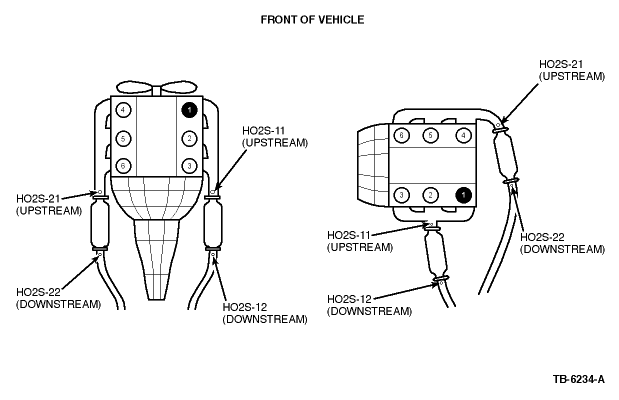
Refer to Figure 1 to better understand the HO2S sensor names and locations. Regardless of how the engine is mounted in the vehicle, conventional or transverse, the HO2S naming convention stays the same in relationship to engine banks 1 and 2. Bank 1 will always be the bank containing the #1 cylinder.
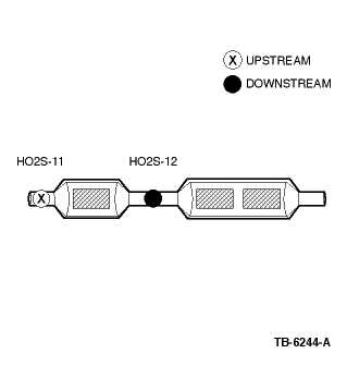
The HO2S Monitor is an on-board strategy designed to monitor the HO2S sensors for a malfunction or deterioration that can affect emissions. Under specific conditions, the fuel control or upstream HO2S sensors ( Figure 1 and Figure 3 ) are checked for proper output voltage and response rate (the time it takes to switch from lean to rich or rich to lean). Downstream HO2S sensors (Figures 1 and 3) used for Catalyst Monitor are also monitored for proper output voltage. Input is required from the ECT or CHT, IAT, MAF, TP and CKP sensors to activate the HO2S Monitor. The Fuel System Monitor and Misfire Detection Monitor must also have completed successfully before the HO2S Monitor is enabled.
The HO2S Monitor DTCs can be categorized as follows:
| HEATED OXYGEN SENSOR (HO2S) MONITOR - HO2S LACK OF SWITCHING | ||
|---|---|---|
| Diagnostic Trouble Code | Description | Possible Causes |
| P1130 - Lack of HO2S-11 Switch, Fuel Trim at Limit | The HEGO Sensor is monitored for switching. The code will set when the HO2S fails to switch due to circuit or fuel at or exceeding a calibrated limit. | Electrical: · Short to VPWR or VREF in harness or HO2S · HO2S circuit shorted to Ground · Water in harness connector · Open circuit · Corrosion or poor mating terminals and wiring · Damaged HO2S · Damaged PCM (other DTCs should be present) Fuel System: · Excessive fuel pressure (stuck fuel pressure regulator, restricted fuel return lines, etc.) · Leaking/contaminated fuel injectors or fuel pressure regulator · Low fuel pressure or running out of fuel (fuel pump concern, fuel supply line restrictions, low fuel level, etc.) · Vapor recovery system (stuck VMV, etc.) Induction System: · MAF contamination · Air leaks between MAF and throttle plate · PCV system / Other vacuum leaks · Improperly seated engine oil dipstick EGR System: · Leaking gasket · Stuck EGR valve / Leaking diaphragm or EVR Base Engine: · Oil overfill · Incorrect cylinder compression · Exhaust leaks before or near the HO2S · Secondary air stuck on |
| HEATED OXYGEN SENSOR (HO2S) MONITOR - HO2S LACK OF SWITCHING | ||
|---|---|---|
| Diagnostic Trouble Code | Description | Possible Causes |
| P1131 - Lack of HO2S-11 Switch, Indicates Lean | When an HO2S sensor indicates lean at the end of a test, the system is trying to correct for an over-lean condition. The code is set when the fuel control system no longer detects switching for a calibrated amount of time. | See Possible Causes for DTC P1130 |
| P1132 - Lack of HO2S-11 Switch, Indicates Rich | When an HO2S sensor indicates rich at the end of a test, the system is trying to correct for an over-rich condition. The code is set when the fuel control system no longer detects switching for a calibrated amount of time. | See Possible Causes for DTC P1130 |
| P1137 - Lack of HO2S-12 Switch, Sensor Indicates Lean | The downstream HO2S sensors are forced rich and lean and monitored by the PCM. The code is set if the PCM does not detect the output of the HO2S in a calibrated amount of time. | · Pinched, shorted or corroded
wiring and pins · Crossed sensor wires · Exhaust leaks · Contaminated or damaged sensor |
| P1138 - Lack of HO2S-12 Switch, Sensor Indicates Rich | Same as DTC P1137, but indicating rich. | See Possible Causes for DTC P1137 |
| P1150 - Lack of HO2S-21 Switch, Fuel Trim at Limit | Same as DTC P1130, but opposite bank. | See Possible Causes for DTC P1130 |
| P1151 - Lack of HO2S-21 Switch, Indicates Lean | Same as DTC P1131, but opposite bank. | See Possible Causes for DTC P1130 |
| P1152 - Lack of HO2S-21 Switch, Indicates Rich | Same as DTC P1132, but opposite bank. | See Possible Causes for DTC P1130 |
| HEATED OXYGEN SENSOR (HO2S) MONITOR - HO2S SLOW RESPONSE RATE | ||
|---|---|---|
| Diagnostic Trouble Code | Description | Possible Causes |
| P0133 - HO2S Sensor Circuit Slow Response (HO2S-11) | The HO2S monitor checks the HO2S sensor frequency and amplitude. If during testing, the frequency and amplitude were to fall below a calibrated limit, the code will set. | Electrical: · Shorted/open wiring · PCM Induction System: · MAF sensor (On 4-cylinder engines, if P0133 is present, this could be caused by a MAF issue - on 6- and 8-cylinder engines, this could only be a MAF issue if P0133 and P0153 are both present) · Inlet air leaks (unmetered air) Fuel Concerns: · Poor fuel quality Base Engine: · Exhaust leaks (upstream or near HO2S) HO2S Concerns: · Contaminated HO2S sensor (contamination from the use of silicone-based cleaners and sealants, leaded fuel, excessive oil consumption, etc.) · Deteriorating HO2S sensor |
| P0153 - HO2S Sensor Circuit Slow Response (HO2S-21) | Same as DTC P0133, but Bank 2. | See Possible Causes for DTC P0133 |
| HEATED OXYGEN SENSOR (HO2S) MONITOR - HO2S SIGNAL CIRCUIT MALFUNCTION | ||
|---|---|---|
| Diagnostic Trouble Code | Description | Possible Causes |
| P0131 - HO2S Sensor Circuit Out of Range Low Voltage (HO2S-11) | The HO2S sensor is monitored for a negative voltage known as Characteristic Shift Downward (CSD). If the sensor is switching from 0 volts to -1 volts during testing and DTC P0131 is present, the PCM will be in FMEM. | Electrical: · Contaminated HO2S sensor or connector (coolant, water, silicone, fuel, oil, etc.) · Chafed/damaged wiring · Crossed HO2S signal/signal return wiring · PCM |
| P0136 - HO2S Sensor Circuit Malfunction (HO2S-12) | The downstream HO2S sensor(s) are continuously checked for maximum and minimum voltages. The code will set when the voltages fail to meet the calibrated limits. | · Disconnected sensor · Pinched, shorted, corroded wiring or pins · Crossed sensor wires · Exhaust leaks · Contaminated or damaged sensor · Chafed/damaged wiring |
| P0151 - HO2S Sensor Circuit Out of Range Low Voltage (HO2S-21) | Same as DTC P0131, but Bank 2. | See Possible Causes for DTC P0131 |
| P0156 - HO2S Sensor Circuit Malfunction (HO2S-22) | Same as DTC P0136, but Bank 2. | See Possible Causes for DTC P0136 |
| HEATED OXYGEN SENSOR (HO2S) MONITOR - HO2S SIGNAL CIRCUIT MALFUNCTION | ||
|---|---|---|
| Diagnostic Trouble Code | Description | Possible Causes |
| P0135 - HO2S Sensor Heater Circuit Malfunction (HO2S-11) | During testing, the HO2S heaters are checked for opens/shorts and excessive current draw. The code will set when current draw exceeds a maximum calibrated limit or falls below a minimum calibrated limit and/or an open or short is detected. | · Blown fuse · Short to VPWR in harness or HO2S · Water in harness connector · Open VPWR or GND circuit · Low battery voltage · Poor electrical connections from PCM to HO2S sensor · HO2S heater · PCM |
| P0141 - HO2S Sensor Heater Circuit Malfunction (HO2S-12) | Same as DTC P0135, but downstream Bank 1. | See Possible Causes for DTC P0135 |
| P0155 - HO2S Sensor Heater Circuit Malfunction (HO2S-21) | Same as DTC P0135, but Bank 2. | See Possible Causes for DTC P0135 |
| P0161 - HO2S Sensor Heater Circuit Malfunction (HO2S-22) | Same as DTC P0141, but downstream Bank 2. | See Possible Causes for DTC P0135 |
| HEATED OXYGEN SENSOR (HO2S) MONITOR - EXHAUST TEMPERATURE OUT OF RANGE, O2 SENSOR TEST NOT COMPLETED | ||
|---|---|---|
| Diagnostic Trouble Code | Description | Possible Causes |
| P1127 - Exhaust Not Warm Enough, Downstream Sensor Not Tested | The HEGO monitor uses an exhaust temperature model to determine when the HO2S heaters can safely be turned on. The code is set when the inferred exhaust temperature is below a minimum calibrated value. | · Engine not operating
long enough prior to performing KOER self-test · Exhaust temperature not warm enough · Pre-existing P0135, P0141, P0155, P0161 |
| HEATED OXYGEN SENSOR (HO2S) MONITOR - SWAPPED HO2S CONNECTOR | ||
|---|---|---|
| Diagnostic Trouble Code | Description | Possible Causes |
| P1128 - Upstream Oxygen Sensors Swapped from Bank 1 (HO2S-11) to Bank 2 (HO2S-21) | The HEGO monitor checks and determines if the HO2S signal response for a KOER fuel shift corresponds to the correct engine bank. The code is set when the expected HO2S response is seen on the opposite bank. | · Crossed HO2S harness
connectors - Bank to Bank (upstream) · Crossed HO2S wiring at 104-pin PCM connector or at the HO2S connectors |
| P1129 - Downstream Oxygen Sensors Swapped from Bank 1 (HO2S-12) to Bank 2 (HO2S-22) | Same as DTC P1128, but downstream. | See Possible Causes for DTC P1128 |
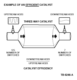
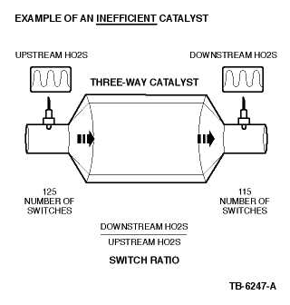
The Federal Test Procedure Catalyst Monitor monitors for deterioration in the catalyst system and illuminates the MIL when tailpipe emissions exceed the appropriate HC emission thresholds. The Catalyst Monitor is enabled after the upstream and downstream HO2S sensors have been tested and verified to be functional. This monitor relies on the front and rear heated oxygen sensors (HO2S) to infer catalyst efficiency based upon oxygen storage capacity. Under normal closed loop fuel conditions, high efficiency catalysts have oxygen storage which makes the switching frequency of the rear HO2S quite slow compared with the frequency of the front HO2S. As catalyst efficiency deteriorates, its ability to store oxygen declines, and the rear HO2S begins to switch more rapidly, approaching the frequency of the front sensor. In general, as catalyst efficiency decreases, the switch ratio increases from a switch ratio of 0 for a low mileage catalyst to a switch ratio of 0.8 or 0.9 for a low efficiency catalyst.
Some vehicles will monitor substantially less than the entire catalyst volume in order to meet the stringent catalyst monitoring malfunction thresholds. In many cases, only the front, light-off catalyst is monitored.
| NOTE: | THE CATALYST MONITOR ON SOME EARLY OBD II VEHICLES (SOME 1994-1996 VEHICLES) WAS REFERRED TO AS THE "STEADY-STATE CATALYST MONITOR" AS OPPOSED TO THE "FTP CATALYST MONITOR" (DESCRIBED ABOVE) THAT IS MOST COMMON FOR VEHICLES BUILT AFTER 1996. BELOW IS A BRIEF DESCRIPTION OF THE STEADY-STATE CATALYST MONITOR: |
The Steady-State Catalyst Monitor performs a 20 second test during steady state rpm and load conditions. The Monitor transfers closed loop fuel control from the front to the rear O2 sensors. The Monitor then observes the switching frequency and compares it to a threshold frequency stored in an rpm/load table. A frequency higher than the maximum calibrated threshold indicates a malfunction.
The Catalyst Monitor DTCs can be categorized as follows:
| CATALYST EFFICIENCY MONITOR | ||
|---|---|---|
| Diagnostic Trouble Code | Description | Possible Causes |
| P0420 - Catalyst System Efficiency Below Threshold (Bank 1) | Indicates Bank 1 catalyst system efficiency is below the acceptable threshold. | · Malfunctioning ECT/CHT · High fuel pressure · Damaged exhaust manifold · Cylinder misfiring · HO2S wiring concerns (shorted or chafed, bent pins, etc.) · Damaged exhaust system pipe · Damaged muffler/tailpipe assembly · Retarded spark timing Damaged Catalytic Converter: · Use of leaded fuel · Oil contamination/consumption · Silicone contamination (sealants/cleaners) |
| P0430 - Catalyst System Efficiency Below Threshold (Bank 2) | Same as DTC P0420, but opposite bank. | See Possible Causes for DTC P0420 |
The Fuel System Monitor is an on-board strategy designed to monitor the fuel trim system. The fuel control system uses fuel trim tables stored in the PCM's KAM to compensate for variability in fuel system components due to normal wear and aging. Fuel trim tables are based on vehicle speed and engine load. During closed loop vehicle operation, the fuel trim strategy learns the corrections needed to correct a "biased" rich or lean fuel system. The correction is stored in the fuel trim tables. The fuel trim has two means of adapting; a LONGFT and a SHRTFT. LONGFT relies on the fuel trim tables and SHRTFT refers to the desired air/fuel ratio parameter "LAMBSE". LAMBSE is calculated by the PCM from HO2S inputs and helps maintain a 14.7:1 air/fuel ratio during closed loop operation. SHRTFT and LONGFT work together. If the HO2S indicates the engine is running rich, the PCM will correct the rich condition by moving SHRTFT in the negative range (less fuel to correct for a rich combustion). If after a certain amount of time SHRTFT is still compensating for a rich condition, the PCM "learns" this and moves LONGFT into the negative range to compensate and allows SHRTFT to return to a value near 0%. Input from the ECT or CHT, IAT, and MAF sensors is required to activate the fuel trim system, which in turn activates the Fuel System Monitor. Once activated, the Fuel System Monitor looks for the fuel trim tables to reach the adaptive clip (adaptive limit) and LAMBSE to exceed a calibrated limit. The Fuel System Monitor will store the appropriate DTC when a fault is detected as described below.
The Fuel System Monitor DTCs can be categorized as follows:
| FUEL SYSTEM MONITOR | ||
|---|---|---|
| Diagnostic Trouble Code | Description | Possible Causes |
| P0148 - Fuel Delivery Error | At least one bank lean at wide open throttle. | Fuel System: · Severely restricted fuel filter · Severely restricted fuel supply line |
| P0171 - System Too Lean (Bank 1) | The Adaptive Fuel Strategy continuously monitors fuel delivery hardware. The code is set when the adaptive fuel tables reach a rich calibrated limit. | Fuel System: · Contaminated fuel injectors · Low fuel pressure or running out of fuel (fuel pump, filter, fuel supply line restrictions) · Vapor recovery system (VMV) Induction System: · MAF contamination · Air leaks between the MAF and throttle body · Vacuum leaks · PCV system concern · Improperly seated engine oil dipstick EGR System: · Leaking gasket · Stuck EGR valve · Leaking diaphragm or EVR Base Engine: · Exhaust leaks before or near the HO2S · Secondary air concern Powertrain Control System: · PCM concern |
| P0174 - System Too Lean (Bank 2) | Same as DTC P0171, but Bank 2. | See Possible Causes for DTC P0171 |
| FUEL SYSTEM MONITOR | ||
|---|---|---|
| Diagnostic Trouble Code | Description | Possible Causes |
| P0172 - System Too Rich (Bank 1) | The Adaptive Fuel Strategy continuously monitors fuel delivery hardware. The code sets when the adaptive fuel tables reach a lean calibrated limit. | Fuel System: · Excessive fuel pressure · Leaking/contaminated fuel injectors · Vapor recovery system concern Base Engine: · Oil overfill · Cam timing concern · Low cylinder compression · Excessive engine wear Powertrain Control System: · PCM concern Induction System: · MAF contamination |
| P0175 - System Too Rich (Bank 2) | Same as DTC P0172, but Bank 2. | See Possible Causes for DTC P0172 |
To further clarify this, see the more detailed scenario as follows:
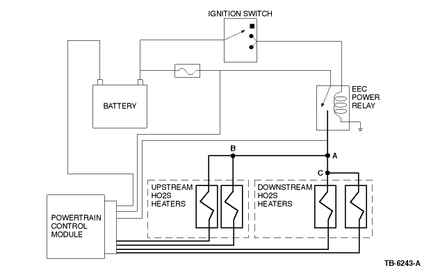
A vehicle comes in with a MIL On concern. KOEO self test reveals DTCs P0135 and P0155 (HTR-11 and HTR-21 circuit malfunction), with no other DTCs present. The most likely cause of these DTCs would be something in the heater power circuit that both of these HO2S sensors have in common (Example: open or shorted heater circuit wiring or splice). It is highly unlikely that multiple sensors would fail at the same time. When multiple DTCs of this nature are encountered, reviewing the appropriate wiring diagram(s) can help to isolate possible areas of concern. When reviewing the wiring diagram, look for things that the affected sensors have in common.
In this example, the most likely cause of DTCs P0135 and P0155 (with no other DTCs present) would be a concern with Splice "B" (refer to Figure 2 ).
| NOTE: | THIS ILLUSTRATION IS ONLY AN EXAMPLE. SPLICE NAMES "A", "B", AND "C" ARE USED IN THIS EXAMPLE FOR CONVENIENCE ONLY. ON AN ACTUAL VEHICLE, SPLICE NAMES WILL DEPEND ON THE CIRCUIT NUMBER FOR THE VEHICLE UNDER REPAIR. NOTE ALSO THAT THIS FIGURE IS NOT INTENDED TO SHOW ALL SPLICES/CONNECTIONS ON ALL VEHICLES. OTHER EEC CIRCUITS, NOT SHOWN, MAY ALSO BE SPLICED IN WITH THE CIRCUITS SHOWN. |
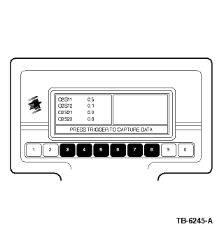
In this example, the vehicle (equipped with a 4-cylinder engine) has one upstream and one downstream HO2S. Notice that the NGS (scan tool) display shows two upstream and two downstream HO2S PIDs, and that the "unused" HO2S sensor PIDs display "0" volts.
Example: In the event of an ignition-related misfire, you might expect a rich HO2S reading, due to the amount of unburned fuel in the exhaust system. However, there is also a large amount of unburned oxygen, since no combustion took place in the misfiring cylinder. Since the HO2S senses oxygen only, it would report a lean condition in this particular situation.
| NOTE: | IF A CATALYST IS DETERMINED TO HAVE LOW EFFICIENCY AND REQUIRES REPLACEMENT, REPLACEMENT OF THE DOWNSTREAM HO2S SENSORS WILL NOT BE NECESSARY. |
Examples: Loose, leaking or disconnected vacuum lines, intake manifold gaskets or O-rings, throttle body gaskets, brake booster, air inlet tube, stuck/frozen/aftermarket PCV valve, unseated engine oil dipstick, MAF reading lower than normal, etc.
Examples: Low fuel pressure (fuel pump, fuel filter, fuel leaks, restricted fuel supply lines), fuel injector concerns, etc.
Examples: Exhaust system leaks upstream or near HO2S, malfunctioning Secondary Air Injection system.
At idle, an engine requires only a small volume of fuel. Due to the fact that there is a small volume of fuel needed at idle, a restriction in the fuel supply line in many cases will not cause the fuel pressure to be low. When the vehicle is under a load, the engine requires much more fuel than at idle. Under a load, a restriction in the fuel supply line will prevent the high rate of fuel flow that is needed to maintain the correct fuel pressure.
INFORMATION ONLY
623000, 690000, 698298
