
new 2/21/03
from http://www.babcox.com/editorial/us/us120232.htm
I have an extremely interesting Diagnostic Dilemma to share with you this month. This vehicle was diagnosed by my friend and fellow driveability technician, Aaron Koeppen of Falls Tire and Auto Care in Menomonee Falls, WI. Aaron was kind enough to share his data and diagnosis with all of us; I only provided a couple of opinions via the phone.
The vehicle in question is a 1997 Ford Taurus SHO with a 3.4L vin W V8 engine and about 79,000 miles on the odometer. The complaint is that the engine stalls very intermittently (approximately one out of 20 stops) when coming to a stop. The engine will restart, and it may run well. Other times, after stalling, the restart may be poor and the engine will barely run for two to three minutes. The MIL was not and has not been illuminated. Also, a random miss was felt at times. This miss would occur in the shop and while driving. It did not seem to be cylinder specific as it was very slight (not as if a cylinder dropped out).
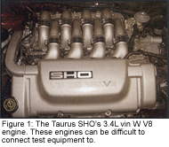
And if the intermittent stalling problem wasn’t challenging enough, these engines can be difficult to both work on and connect test equipment to. See Figure 1.
The first step was to connect a scan tool. A pending P1121 was pulled. Per Ford, "Continuous Memory DTC P1121 indicates the TP sensor is inconsistent with the MAF sensor." The PCM performs a rationality check between the TP and MAF. The Ford service literature asks two questions that describe what the PCM might be looking at to set this code.
1. Is the TP pid greater than 49.02% (2.44 volts) and the Load pid reading less than 25%?
2. Is the TP pid reading less than 4.90% (0.24 volts) and the Load pid reading greater than 60%?
These two questions seem to define the P1121 nicely. Either of these two conditions (high TP voltage with a low load or a high load with a low TP voltage) will fail the rationality check.
Aaron’s next step was to capture the stall with the scan tool and gas analyzer. Both tools provide a wealth of diagnostic data and usually can provide a diagnostic direction.
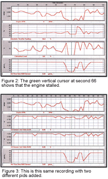
Figure 2 shows an EASE scan tool recording of a stall occurring in his shop.
The green vertical cursor at about second 66 shows that the engine stalled. The engine ran poorly just before the stall and after the stall on a restart. Do you see any issues with this recording? The obvious one appears to be the MAF reading on the bottom chart of Figure 2. Note how the reading appears to be stuck at exactly 50 grams/second. Even with the engine stalled and no rpm, the MAF pid shows 3.83 grams/sec. Additionally, the load pid seems quite high compared to the TP pid. The P1121 appears to be properly setting.
Figure 3 is this same recording with two different pids added. They are Bank 1 Sensor 1 O2 sensor and Bank 2 Sensor 1 O2 sensor. For this entire 100-second recording, they are indicating a rich exhaust on both banks.
Well, with the MAF showing 50 grams/sec of airflow, we would expect the PCM to add some fuel to the base fuel injector pulsewidth calculation. Figure 4 shows another recording of this SHO when the engine started to run poorly.
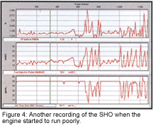
In Figure 4, only Bank 1 pulsewidth is shown, but Bank 2 was very similar. Generally, we would expect to see a fuel command at idle somewhere between 3 and 5 milliseconds. According to the scan tool, we are seeing a fuel command between 10 and 20 milliseconds. This was confirmed with a lab scope on one of the sequentially fired fuel injectors. See Figure 5 on page 36.
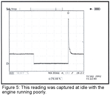
Figure 5 was captured at idle with the engine running poorly. On-time is approximately 19 milliseconds. Of course, this is a really rich fuel command.
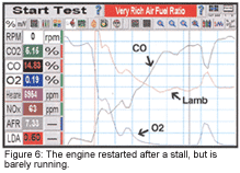
Finally, let’s see what the gas analyzer says. Figure 6 on page 36 was captured during this same condition. The engine was restarted after a stall. The engine is barely running, and if it were on the road it would be almost undriveable.
The vertical cursor (three divisions in from the right side) corresponds to the gas values shown in the boxes. The CO is very high at 14.83%, and the HC is equally high at 6,954 ppm. The engine is super rich. Lambda (LDA in the box) is 0.50, which means the air/fuel ratio is 50% richer than stoichiometric. Generally speaking, Lambda of 1 plus or minus 5% is acceptable. Fundamentally, we have an engine that is overfueling itself. On decel, the engine stalls with this rich air/fuel ratio. Sometimes on a restart, the engine continues to run very rich. This is the problem.
Let’s summarize what we know to this point. The engine stalls and runs poorly due to the PCM commanding a very, very rich fuel command. The obvious input, which appears to be skewed, is the MAF sensor. The PCM has set a P1121, which indicates a rationality issue between the TP and MAF. Aaron also noted that performing a KOEO check of the MAF sensor after a stall would show a fixed airflow reading of between 3 and 4 grams/second.
Here’s the kicker. With this problem occurring, Aaron scoped the MAF input signal line and saw no problem. That’s right! With the scan tool showing almost 50 grams/second of airflow, the analog input from the MAF sensor to the PCM was good at about 0.8 volts.
That old computer expression "garbage in, garbage out" does not apply in this situation. The MAF input is good, but the PCM thinks it is much higher than what it really is. Either the PCM is making a bad decision on its own or "something" is telling the PCM to make a bad decision.
PCM feeds and grounds were checked and found to be good. No relays or solenoids were found to be drawing excessive current. Could it be an internal PCM failure? Sure it could, but… someone prior to Aaron working on this SHO had already installed a Ford PCM. What are the chances of two PCMs failing in the same way? It is not impossible, but it is pretty slim.
The clues on every stall were consistent. The PCM was overfueling the engine based on an incorrect MAF reading. Yet, the analog input from the MAF sensor was good.
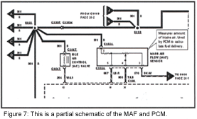
Figure 7 shows a partial schematic of the MAF and PCM. This MAF has four wires:
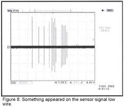
Aaron decided to scope each wire very carefully. With the engine running well, no problem was seen on any of the four wires. While road-testing with his scope connected to these wires, the problem occurred. Scan data showed MAF increasing, yet the scope showed the analog input to be OK. However, something appeared on the sensor signal low wire (tan/light blue wire). That something is shown in Figure 8 on page 36.
There is noise on the signal low line. Note the vertical scale of 10 volts/div. Some of those spikes are almost 60 volts peak-to-peak. Well, there aren’t too many systems on the engine that can produce that type of voltage. As you probably have already suspected, this is ignition related.
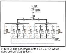
This 3.4L SHO uses coil-on-plug ignition. The PCM houses a primary driver for each coil. Figure 9 shows the schematic.
Though I haven’t mentioned this until now, Aaron had scoped all eight coils. The primary pattern on five of them looked pretty bad. So, he knew there were some ignition issues. At the time, there was no obvious connection between primary ignition and the MAF sensor.
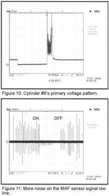
However, now there was a connection. Back in the shop, Aaron compared coil primary voltage to the MAF sensor signal low line. Figure 10 shows cylinder #8’s primary voltage pattern, while Figure 11 shows more noise on the MAF sensor signal low line. I think you will agree that this is more than just a coincidence.
The primary voltage pattern shown in Figure 10 was captured at idle. Note the timebase of 400 microseconds/div (0.4 milliseconds/div). This is a coil failure.
The noise seen on the spark line goes right into the PCM. How does this noise influence the MAF sensor in this way? I certainly don’t know for sure, but there are a couple of educated guesses that can be made.
First, the noise was only seen on the MAF sensor signal low line. The chances of the #8 coil inducing this noise into just that one wire are unlikely. Since the signal low line is a dedicated MAF ground to the PCM, it shares no other input sensor nor does it tie to an engine ground. Aaron and I both think that the noise from the #8 coil entered into the PCM via the primary control line and somehow internal to the PCM was connected to the MAF sensor signal low line. When the ignition coil acted up, the PCM saw this noise on the MAF signal low line. The MAF sensor signal line and signal low line are probably differential inputs to the PCM. Said another way, the PCM measures the voltage difference between those two wires and makes an internal decision regarding airflow. The excessive voltage differential due to the spikes confused the PCM regarding actual airflow.
In Figure 11, Aaron is turning the coil on and off by using a special tool known as a COP III. The noise on the MAF sensor signal low line disappears with the #8 ignition coil turned off. This confirms the diagnosis.
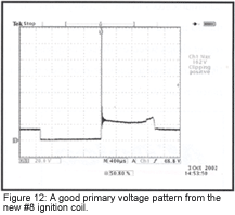
The vehicle was fixed by replacing the #8 coil and four other ignition coils that had noisy spark lines. Figure 12 shows a good primary voltage pattern from the new #8 ignition coil.
Well, I hope you enjoyed this article. This was certainly a true "Diagnostic Dilemma." While this type of problem is not an everyday occurrence (fortunately), ignition noise does exist and can cause some pretty unusual problems for us.
Special thanks to Aaron Koeppen of Falls Tire and Auto Care in Menomonee Falls, WI, for sharing his Diagnostic Dilemma with us.
I recently had a problem with my wife's 97 SHO, after pulling my hair out and changing MAF sensor,TPS, and ISC I was ready to change the computer when I found this article. http://www.babcox.com/editorial/us/us120232.htm My problem was slightly different but basically the same (bad coil pack feeding back thur MAF). I changed all 8 plugs and coil packs and fixed the problem. Just wanted to pass it on.